
(There's a joke in the title and background picture...see if you can get it. Hint: "Salt-n-Pepa")
Every designer understands - in principle - that tighter tolerances add cost and should be applied only when necessary. What's harder to see from behind the CAD screen is how often that cost is paid unnecessarily, not because the application demands it, but because the print didn't fully reflect how the part actually works.
The Easy Way
The typical path-of-least-resistance is straightforward: assign coordinate dimensions, apply a bilateral tolerance, and move on. (e.g., 1.0000" ±0.0005") It's fast, it's familiar, and it communicates something—just not always the right thing. Coordinate tolerancing treats every dimension as equally important, applies the same logic to a precision mating bore and a clearance pocket, and says nothing about how the part behaves in its assembled, operating condition.
The result is a set of manufacturing requirements that may be significantly more demanding than the application needs. Manufacturers like Infinity hold what the print specifies. If the print specifies it uniformly, we treat it uniformly and the customer pays for that uniformity whether or not the application actually needs it.
Sometimes, coordinate dimensions are fine; but many times there's a better way.
A Better Way (Thank you Stanley Parker)
Geometric Dimensioning and Tolerancing (GD&T) exists to connect tolerances to function. A well-constructed GD&T callout isn't just a tighter or looser number - it's a statement about how a surface, feature, or relationship behaves "in use". Flatness speaks to how a mating face seats. Perpendicularity addresses how a bore aligns in an assembly. True position defines where a feature needs to be relative to the datum structure that actually matters for fit and function - not relative to whatever edge happened to be convenient to dimension from.
Used well, GD&T allows tolerance zones to be sized by what the application can tolerate, not by convention, habit or convenience. It communicates intent. And when intent is clear, the shop can make intelligent process decisions - where to spend time, where there's room to be efficient, and what inspection steps actually matter versus what's just checking boxes.
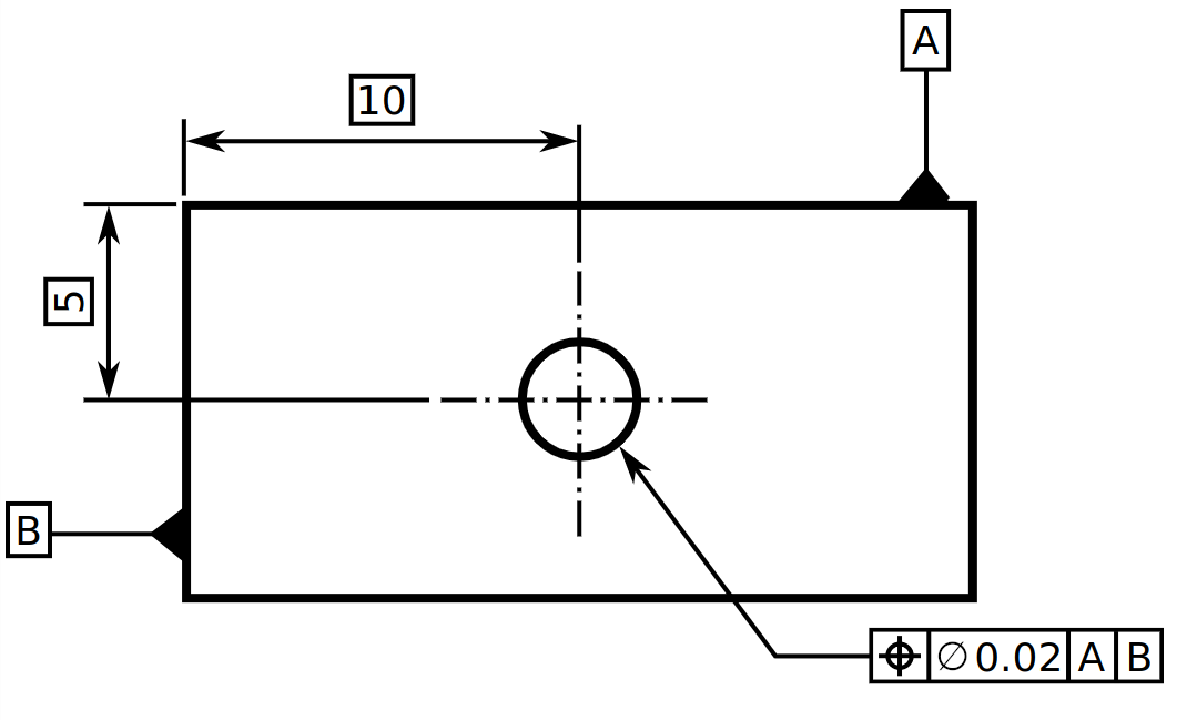
The classic example most engineers already know: a coordinate bilateral tolerance creates a square tolerance zone. The equivalent true position callout at the same functional limit yields a circular zone with meaningfully more usable area. The part is more producible and functionally identical. That's not a trick — it's the system working as designed.
The Conversation Worth Having
Infinity sees a wide range of prints. The ones that work best - for the customer's budget, for our process planning, and for the final part - are the ones where the tolerances reflect design decisions, not defaults. When there's an opportunity to talk through a print before a job is quoted, that conversation almost always pays off. Sometimes it confirms the callouts are right. Sometimes it surfaces a feature or two where a revision saves real money without changing what the part needs to do.
GD&T is a language for communicating functional intent. The more fluently a print speaks it, the better the outcome on both ends of the job.
We're always happy to talk about it — your print, your tolerances, all the good things and the bad things that may be. That conversation costs nothing. The ones we don't have sometimes do.